Light source and light source controller
Flash controller
A strobe controller is a high-efficiency LED light source controller. Unlike conventional light source controllers, a strobe controller switches its output voltage on and off according to a preset pulse width to control the flickering illumination of the LED light source. When the output voltage is on, its value is generally more than twice that of a conventional controller (for example, for a 24VDC LED light source, its output voltage can be as high as 48VDC), and the maximum conduction time does not exceed 1000µs. Therefore, the strobe controller can significantly increase the instantaneous brightness of the LED light source, and at the same time, because the light source is lit for a shorter time, it suppresses the internal temperature rise of the LED, thereby greatly extending the life of the light source.
▶ Application Scope
The width of the output voltage pulse (i.e., the illumination time of the light source) can be set from 1µs to 1000µs, and the pulse width ratio can be set to increase the instantaneous brightness of the light source by more than 300% and extend the life of the light source. It automatically outputs a camera trigger signal and ensures that the camera is triggered synchronously to capture images after the light source is illuminated. It can operate in external trigger mode, internal trigger mode, and constant-on mode. When the load current exceeds the controller's maximum value or a short circuit occurs, the controller automatically protects itself and stops the output. It can communicate with a PC via RS232 or a network port. It has two installation methods: DIN rail mounting with clips and screw fixing (removing the feet).
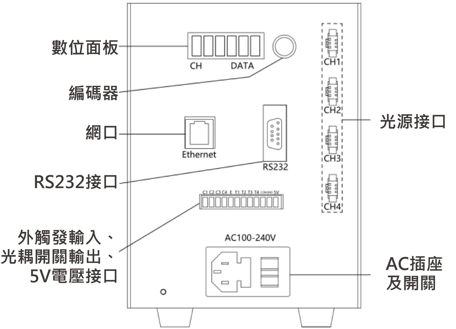
▶ Panel Description: Digital Panel Display
▶ Controller parameters
| model | Input voltage | Output voltage | Total power | aisle | Light source interface | Single channel maximum power | Communication methods | Trigger voltage | Trigger delay |
|---|---|---|---|---|---|---|---|---|---|
| HSC-48V50W-4T | 100-240VAC | 48VDC | 3000W | 4 | SM3P female connector | 2000W | serial port | 12-24V | <7us |
| HSC-48V120W-4T | 100-240VAC | 48VDC | 6000W | 4 | SM3P female connector | 2000W | serial port | 12-24V | <7us |
| HWSC-48V60W-4T | 100-240VAC | 48VDC | 3000W | 4 | SM3P female connector | 2000W | Serial port & Ethernet port | 12-24V | <7us |
| HWSC-48V120W-4T | 100-240VAC | 48VDC | 6000W | 4 | SM3P female connector | 2000W | Serial port & Ethernet port | 12-24V | <7us |